Warp3D Nova: 3D At Last - Part 2
It's finally time to render in 3D using Warp3D Nova. Last time we covered the theory; now it's time to put it into practise. There's still a lot to learn though, so brace yourself.
Step 1: Preparation
Start by creating a new project in CodeBench (or whatever editor you're using) called Tutorial5. Copy the Context, Init, and Util modules from the previous tutorial. Be sure to copy both the *.c source files and *.h headers. Also copy FAIL_ON_ERROR() and compileShader() to Tutorial5.c, along with the header includes (e.g., #include <Warp3DNova/Warp3DNova.h>). We'll be needing all of those.
NOTE: You could just copy and modify the previous tutorial's source-code, but the large number of changes could get confusing.
Now add the following skeleton main() function to Tutorial5.c:
int main(int argc, const char **argv) {
	int retCode = 0; // Default to returning success
	RenderContext *renderContext = NULL;
	BOOL quit = FALSE;
	BOOL refreshWindow = FALSE;
	BOOL resizeWindow = FALSE;
	W3DN_ErrorCode errCode;

	W3DN_Shader *vertShader = NULL;
	W3DN_Shader *fragShader = NULL;
	W3DN_ShaderPipeline *shaderPipeline = NULL;
	W3DN_VertexBuffer *vbo = NULL;
	W3DN_DataBuffer *dbo = NULL;
	W3DN_LogLevel logLevel = W3DNLL_ERROR;

	if(argc >= 2) {
		if(strcmp(argv[1], "-v") == 0) {
			// Enable debug logging for the compiler (spits out lots of info)
			logLevel = W3DNLL_DEBUG;
		}
	}

	// For requester titles...
	setProgName(PROG_TITLE);

	// Open the libraries
	// NOTE: OpenLibs() already sets up a closeLibs() callback, so no need to close
	// them manually
	if(!openLibs()) {
		// Error messages already displayed...
		return 5;
	}

	// Create the render context
	renderContext = rcCreate(PROG_TITLE, WIDTH, HEIGHT, DSM_DEPTH);
	if(!renderContext) {
		return 10;
	}

	// Will be using the Warp3D Nova context a lot...
	W3DN_Context *context = renderContext->context;

	// Enable depth testing
	// ##### IMPLEMENT ME! ######


	// -- Set up the shaders --
	// Compile the shaders
	vertShader = compileShader(context, "Colour3D.vert.spv", logLevel);
	fragShader = compileShader(context, "Colour3D.frag.spv", logLevel);
	if(!vertShader || !fragShader) {
		showErrorRequester("Couldn't compile shaders.");
		goto CLEANUP;
	}

	// Create the shader pipeline
	errCode = W3DNEC_SUCCESS;
	shaderPipeline = context->CreateShaderPipelineTags(&errCode,
		W3DNTag_Shader, vertShader, W3DNTag_Shader, fragShader, TAG_DONE);
	FAIL_ON_ERROR(errCode, "CreateShaderPipelineTags");

	// Set the shader pipeline as current
	errCode = context->SetShaderPipeline(NULL, shaderPipeline);
	FAIL_ON_ERROR(errCode, "CreateShaderPipelineTags");


	// -- Create the Geometry to be Rendered --
	// ##### IMPLEMENT ME! ######


	// - Create the Data Buffer Object (DBO) -
	// This contains the vertex shader's constant data
	// ##### IMPLEMENT ME! ######


	// -- Setting the initial view --
	// ##### IMPLEMENT ME! #####


	// -- Main Loop --
	refreshWindow = TRUE; // Want to perform an initial render

	while(!quit) {
		// Putting this here so that we can perform an initial render without needing to wait
		// for a message to come in
		if(refreshWindow) {
			// -- Render the Image --
			// ##### IMPLEMENT ME! #####

			// Submit to the GPU for rendering
			uint32 submitID = context->Submit(&errCode);
			if(!submitID) {
				// This should never happen...
				printf("context->Submit() failed (%u): %s\n",
					errCode, IW3DNova->W3DN_GetErrorString(errCode));
				retCode = 10;
			}

			// Swap the buffers, so that our newly rendered image is displayed
			rcSwapBuffers(renderContext);

			// All done
			refreshWindow = FALSE;
		}

		// Wait for an event to happen that we need to respond to
		struct Window *window = renderContext->window;
		IExec->WaitPort(window->UserPort);
		struct IntuiMessage *msg;
		while ((msg = (struct IntuiMessage *) IExec->GetMsg (window->UserPort))) {
			switch (msg->Class)
			{
			case IDCMP_NEWSIZE:
				// A resize occurred, need to refresh the window
				resizeWindow = TRUE;
				break;
			case IDCMP_REFRESHWINDOW:
				refreshWindow = TRUE;
				break;
			case IDCMP_CLOSEWINDOW:
				// The user says quit!
				quit = TRUE;
				break;
			default:
				; // Do nothing
			}
			IExec->ReplyMsg((struct Message *) msg);
		}

		if(resizeWindow) {
			// Adjust the render context for the resize
			rcDoResize(renderContext);

			// Now trigger a refresh
			refreshWindow = TRUE;

			// All done
			resizeWindow = FALSE;
		}
	}


	// -- Cleanup --
CLEANUP:
	if(dbo) {
		context->DestroyDataBufferObject(dbo);
		dbo = NULL;
	}
	if(vbo) {
		context->DestroyVertexBufferObject(vbo);
		vbo = NULL;
	}
	if(shaderPipeline) {
		context->DestroyShaderPipeline(shaderPipeline);
		shaderPipeline = NULL;
	}
	if(fragShader) {
		context->DestroyShader(fragShader);
		fragShader = NULL;
	}
	if(vertShader) {
		context->DestroyShader(vertShader);
		vertShader = NULL;
	}
	if(renderContext) {
		rcDestroy(renderContext);
		renderContext = NULL;
	}

	return retCode;
}
We'll add more code in the areas marked with ##### IMPLEMENT ME! ######.
If you look closely you'll see a new object type in the code above: W3DN_DataBuffer *dbo, which is a Data Buffer Object (DBO). DBOs are used to store shader constants, a.k.a., "uniform variables" in OpenGL terminology. We'll be using a DBO to pass the Model-View-Projection (MVP) matrix to the shader so it can transform vertices from model to screen coordinates.
Step 2: 3D Mathematics
We need a 3D vector/matrix library to perform various 3D transformations. You could write one yourself, but there are several ready-made to choose from. I'm going to use kazmath: https://github.com/Kazade/kazmath
Kazmath is a 3D maths library that's designed for OpenGL. It's also perfect for Warp3D Nova, so get it now. You can download a copy or use SGit to checkout the code.
Copy the kazmath directory into your project directory, and add it to your project. I highly adding the files to "kazmath" sub-categories. This keeps your project organised. You can add sub-categories by right-clicking on "header files" or "source files," and selecting "Add SubCategory."
Model, View, & Projection Matrices
If you don't know what Model, View and Projection (MVP) matrices are, then go back to part 1 and find out. The code won't make sense unless you understand what those matrices do.
In main(), create modelMatrix, viewMatrix, and projectionMatrix variables. They're 4x4 matrices, so make them of type kmMat4:
kmMat4 modelMat; // The cube's pose
kmMat4 viewMat; // The camera's view matrix
kmMat4 projectionMat; // The camera's projection matrix
These matrices need to be initialised. Insert the following in the section titled "Set the initial view":
// Setting the initial model matrix
kmMat4 rotMat;
kmMat4RotationX(&modelMat, M_PI / 4);
kmMat4RotationY(&rotMat, M_PI / 4);
kmMat4Multiply(&modelMat, &rotMat, &modelMat);

// Set the view
kmMat4Translation(&viewMat, -CAM_STARTPOS_X, -CAM_STARTPOS_Y, -CAM_STARTPOS_Z);

// Set the projection
resize(context, WIDTH, HEIGHT, &projectionMat);
The first section rotates the model by 45 degrees (∏/4 radians) about the x and y axes. This orientation makes the cube we'll render look more interesting. The view matrix simply translates the camera to a predefined position. A good place to put it is:
// The camera's start position
#define CAM_STARTPOS_X 0.0f
#define CAM_STARTPOS_Y 0.0f
#define CAM_STARTPOS_Z 150.0f
The camera looks straight down the negative z-axis, so moving it along z gives us a nice view.
The projection matrix has to be recalculated every time the window is resized, so that code is put in a resize() function:
/** Sets up the viewport and projection matrix for the display size.
 *
 * @param context pointer to the render context
 * @param width the display width
 * @param height the display height
 * @param projectionMatrix pointer to the 4x4 projection matrix
 */
static void resize(W3DN_Context *context, double width, double height, kmMat4 *projectionMatrix) {
	context->SetViewport(NULL, 0.0, height, width, -height, 0.0, 1.0);
	kmMat4PerspectiveProjection(projectionMatrix, 60.0, width / (float)height, 1.0, 1024.0);
}
Kazmath provides a convenient function to generate the projection matrix. No need to understand exactly what it does. Having said that, this page gives a detailed explanation of OpenGL's projection matrix (which is what we use).
Resize() also has to be called every time the window is resized, so scroll down to the main loop and add it to the if(resizeWindow){} code block:
if(resizeWindow) {
	// Adjust the render context for the resize
	rcDoResize(renderContext);
	resize(context, renderContext->width, renderContext->height, &projectionMat);
The Viewport
The resize() function above has one line that deserves more attention:
context->SetViewport(NULL, 0.0, height, width, -height, 0.0, 1.0);
This line sets the final transformation from clip coordinates to screen coordinates (i.e., pixels). Notice how a negative height is given? The viewport is set in this way because Warp3D Nova's standard coordinates puts the origin in the top left corner, whereas OpenGL puts the origin in the bottom left corner. The line above flips the y axis and moves it to the bottom. That way we can use the OpenGL projection matrix as-is.
The Cube
We'll be rendering a simple cube. The vertex data is similar to the previous tutorial's triangle, but positions are now 3D. It's structured as follows:
/** Encapsulates the data for a single vertex
 */
typedef struct Vertex_s {
	float position[3];
	float colour[4];
} Vertex;
It'll be rendered as a series of triangles. A naive way to do this would be to store every triangle in the Vertex Buffer Object (VBO). That would be wasteful. Each of the cube's vertices (a.k.a., corners) is used by multiple triangles. So, rather than store every triangle, we'll store each vertex once and use an index array to render the triangles.
Each of the cube's faces will be a different colour, so insert the following table into Tutorial5.c:
// Colour constants
static const float opaqueBlack[4] = {0.0f, 0.0f, 0.0f, 1.0f};
static const float red[4] = {1.0f, 0.0f, 0.0f, 1.0f};
static const float green[4] = {0.0f, 1.0f, 0.0f, 1.0f};
static const float blue[4] = {0.0f, 0.0f, 1.0f, 1.0f};
static const float white[4] = {1.0f, 1.0f, 1.0f, 1.0f};
static const float yellow[4] = {1.0f, 1.0f, 0.0f, 1.0f};
static const float aqua[4] = {0.0f, 1.0f, 1.0f, 1.0f};
Now the cube's geometry can be created. Here's the code to create the VBO and the cube's geometry:
// Indices of the vertex and index arrays
const uint32 posArrayIdx = 0;
const uint32 colArrayIdx = 1;
const uint32 indexArrayIdx = 2;

// Create the Vertex Buffer Object (VBO) containing the triangle
float cubeSize_2 = 100.0f / 2.0f; // Half the cube's size
uint32 numSides = 6;
uint32 vertsPerSide = 4;
uint32 numVerts = numSides * vertsPerSide;
uint32 numArrays = 3; // Have position, colour, and index arrays
uint32 indicesPerSide = 2 * 3; // Rendering 2 triangles per side of the cube
uint32 numIndices = indicesPerSide * numSides;
vbo = context->CreateVertexBufferObjectTags(&errCode,
		numVerts * sizeof(Vertex) + numIndices * sizeof(uint32), W3DN_STATIC_DRAW, numArrays, TAG_DONE);
FAIL_ON_ERROR(errCode, "CreateVertexBufferObjectTags");

// Set the VBO's layout
Vertex *vert = NULL;
uint32 stride = sizeof(Vertex);
uint32 posNumElements = sizeof(vert->position) / sizeof(vert->position[0]);
uint32 colourNumElements = sizeof(vert->colour) / sizeof(vert->colour[0]);
uint32 colourArrayOffset = offsetof(Vertex, colour[0]);
uint32 indexArrayOffset = numVerts * sizeof(Vertex);
errCode = context->VBOSetArray(vbo, posArrayIdx, W3DNEF_FLOAT, FALSE, posNumElements,
	stride, 0, numVerts);
FAIL_ON_ERROR(errCode, "VBOSetArray");
errCode = context->VBOSetArray(vbo, colArrayIdx, W3DNEF_FLOAT, FALSE, colourNumElements,
	stride, colourArrayOffset, numVerts);
FAIL_ON_ERROR(errCode, "VBOSetArray");
errCode = context->VBOSetArray(vbo, indexArrayIdx, W3DNEF_UINT32, FALSE, 1,
	sizeof(uint32), indexArrayOffset, numIndices);
FAIL_ON_ERROR(errCode, "VBOSetArray");

// Lock the VBO for access
// NOTE: We're replacing all data in the VBO, so the read range is 0
W3DN_BufferLock *vboLock = context->VBOLock(&errCode, vbo, 0, 0);
FAIL_ON_ERROR(errCode, "VBOLock");

uint32 i = 0;
vert = (Vertex*)vboLock->buffer;

// Front face (red)
vert[i++] = (Vertex){{-cubeSize_2, -cubeSize_2,   cubeSize_2}, {red[0], red[1], red[2], red[3]}};
vert[i++] = (Vertex){{ cubeSize_2, -cubeSize_2,   cubeSize_2}, {red[0], red[1], red[2], red[3]}};
vert[i++] = (Vertex){{ cubeSize_2,  cubeSize_2,   cubeSize_2}, {red[0], red[1], red[2], red[3]}};
vert[i++] = (Vertex){{-cubeSize_2,  cubeSize_2,   cubeSize_2}, {red[0], red[1], red[2], red[3]}};
// Back face
vert[i++] = (Vertex){{ cubeSize_2, -cubeSize_2,  -cubeSize_2}, {green[0], green[1], green[2], green[3]}};
vert[i++] = (Vertex){{-cubeSize_2, -cubeSize_2,  -cubeSize_2}, {green[0], green[1], green[2], green[3]}};
vert[i++] = (Vertex){{-cubeSize_2,  cubeSize_2,  -cubeSize_2}, {green[0], green[1], green[2], green[3]}};
vert[i++] = (Vertex){{ cubeSize_2,  cubeSize_2,  -cubeSize_2}, {green[0], green[1], green[2], green[3]}};
// Left face
vert[i++] = (Vertex){{-cubeSize_2, -cubeSize_2,  -cubeSize_2}, {blue[0], blue[1], blue[2], blue[3]}};
vert[i++] = (Vertex){{-cubeSize_2, -cubeSize_2,   cubeSize_2}, {blue[0], blue[1], blue[2], blue[3]}};
vert[i++] = (Vertex){{-cubeSize_2,  cubeSize_2,   cubeSize_2}, {blue[0], blue[1], blue[2], blue[3]}};
vert[i++] = (Vertex){{-cubeSize_2,  cubeSize_2,  -cubeSize_2}, {blue[0], blue[1], blue[2], blue[3]}};
// Right face
vert[i++] = (Vertex){{ cubeSize_2, -cubeSize_2,   cubeSize_2}, {white[0], white[1], white[2], white[3]}};
vert[i++] = (Vertex){{ cubeSize_2, -cubeSize_2,  -cubeSize_2}, {white[0], white[1], white[2], white[3]}};
vert[i++] = (Vertex){{ cubeSize_2,  cubeSize_2,  -cubeSize_2}, {white[0], white[1], white[2], white[3]}};
vert[i++] = (Vertex){{ cubeSize_2,  cubeSize_2,   cubeSize_2}, {white[0], white[1], white[2], white[3]}};
// Top face
vert[i++] = (Vertex){{ cubeSize_2,  cubeSize_2,  -cubeSize_2}, {yellow[0], yellow[1], yellow[2], yellow[3]}};
vert[i++] = (Vertex){{-cubeSize_2,  cubeSize_2,  -cubeSize_2}, {yellow[0], yellow[1], yellow[2], yellow[3]}};
vert[i++] = (Vertex){{-cubeSize_2,  cubeSize_2,   cubeSize_2}, {yellow[0], yellow[1], yellow[2], yellow[3]}};
vert[i++] = (Vertex){{ cubeSize_2,  cubeSize_2,   cubeSize_2}, {yellow[0], yellow[1], yellow[2], yellow[3]}};
// Bottom face
vert[i++] = (Vertex){{-cubeSize_2, -cubeSize_2,  -cubeSize_2}, {aqua[0], aqua[1], aqua[2], aqua[3]}};
vert[i++] = (Vertex){{ cubeSize_2, -cubeSize_2,  -cubeSize_2}, {aqua[0], aqua[1], aqua[2], aqua[3]}};
vert[i++] = (Vertex){{ cubeSize_2, -cubeSize_2,   cubeSize_2}, {aqua[0], aqua[1], aqua[2], aqua[3]}};
vert[i++] = (Vertex){{-cubeSize_2, -cubeSize_2,   cubeSize_2}, {aqua[0], aqua[1], aqua[2], aqua[3]}};
Insert the code above in main()'s "Create the Geometry to be Rendered" section.
The Index Array
Look carefully at the code to create the VBO. It also allocates space for an index array:
vbo = context->CreateVertexBufferObjectTags(&errCode,
		numVerts * sizeof(Vertex) + numIndices * sizeof(uint32), W3DN_STATIC_DRAW, numArrays, TAG_DONE);
This third array is set to be the index array in the next section. Here's the relevant line from the code above:
errCode = context->VBOSetArray(vbo, indexArrayIdx, W3DNEF_UINT32, FALSE, 1,
	sizeof(uint32), indexArrayOffset, numIndices);
Now, let's generate the index array. Each cube face is made up of two triangles, and those faces are rendered in anti-clockwise order, as is shown below.

So each side's vertex order is: 0, 1, 2, 2, 3, 0. In code, this is:
// Generate the index array
uint32 *idxArray = (uint32*)((uint8*)vboLock->buffer + indexArrayOffset);
i = 0;
for(uint32 j = 0; j < numSides; ++j) {
		uint32 sideBaseIdx = j * vertsPerSide;
	idxArray[i++] = sideBaseIdx + 0;
	idxArray[i++] = sideBaseIdx + 1;
	idxArray[i++] = sideBaseIdx + 2;
	idxArray[i++] = sideBaseIdx + 2;
	idxArray[i++] = sideBaseIdx + 3;
	idxArray[i++] = sideBaseIdx + 0;
}

// Unlock the VBO
// NOTE: We've updated the entire VBO, so the parameters reflect that
errCode = context->BufferUnlock(vboLock, 0, vboLock->size);
FAIL_ON_ERROR(errCode, "BufferUnlock");
Binding the Vertex Attributes
The final vertex array task is to bind the arrays/attributes to the shader inputs:
// Map vertex attributes to indices
// NOTE: The vertex attributes are ordered using the modern GLSL layout(location =  n)
// qualifier (see the vertex shader). This ensures that they're always located at the
// right place, and eliminates the need to call ShaderGetOffset(). Setting fixed
// locations in this manner is highly recommended
uint32 posAttribIdx = 0;
uint32 colAttribIdx = 1;

// Bind the VBO to the default Render State Object (RSO)
errCode = context->BindVertexAttribArray(NULL,
	posAttribIdx, vbo, posArrayIdx);
FAIL_ON_ERROR(errCode, "BindVertexAttribArray");
errCode = context->BindVertexAttribArray(NULL,
	colAttribIdx, vbo, colArrayIdx);
FAIL_ON_ERROR(errCode, "BindVertexAttribArray");
The index array isn't bound because it'll be passed directly to DrawElements().
Shaders
The fragment shader is the same as for the previous tutorial:
#version 140

in vec4 colour;

void main() {
    gl_FragColor = colour;
}
The vertex shader, on the other hand, has to transform incoming vertices by the MVP matrix:
#version 310 es
/** Simple 3D per-vertex colour shader.
 */

in layout(location = 0) vec3 vertPos;
in layout(location = 1) vec4 vertCol;

uniform layout(location = 0) mat4 ModelViewProjectionMatrix;

out vec4 colour;

void main() {
	// Pass the colour through
	colour = vertCol;

	// Transform the position to clip coordinates
	gl_Position = ModelViewProjectionMatrix * vec4(vertPos, 1.0);
}
There are two key lines to look at. First, the MVP matrix uniform variable is created:
uniform layout(location = 0) mat4 ModelViewProjectionMatrix;
Then, incoming vertices are multiplied by that matrix to transform them to clip coordinates:
gl_Position = ModelViewProjectionMatrix * vec4(vertPos, 1.0);
IMPORTANT: Remember that the shaders need to be compiled to SPIR-V form. Have a look at the Hello Triangle tutorial for a refresher on how to create the makefile rules to compile them.
Sending the MVP matrix to the GPU
So far we have the vertex data and the shaders set up. The next task is to send the MVP matrix to the GPU. This is done via a Data Buffer Object (DBO). A DBO is a buffer that can contain data; any data. What that data is depends on the shader reading it.
Shaders store uniform variables in DBOs as a structure. In Warp3D Nova that structure is the same on both the CPU and GPU (same alignment rules), so it helps to create that structure in your CPU code:
/** The structure for the vertex shader's uniform data.
 * IMPORTANT: Keep this synchronized with the shader!
 */
typedef struct VertexShaderData_s {
	kmMat4 mvpMatrix; // ModelViewProjectionMatrix
} VertexShaderData;
Yes, that's a bit redundant with only one uniform, but this'll become important later when you add other variables such as lights.
Let's create the DBO. Add the following code to the "Create the Data Buffer Object (DBO)" section:
// This contains the vertex shader's constant data
// NOTE: Using W3DN_STREAM_DRAW, because we will be updating the matrices
// every time
dbo = context->CreateDataBufferObjectTags(&errCode,
	sizeof(VertexShaderData), W3DN_STREAM_DRAW, 1, TAG_DONE);
if(!dbo) {
	printf("context->CreateDataBufferObjectTags() failed (%u): %s\n",
		errCode, IW3DNova->W3DN_GetErrorString(errCode));
	retCode = 10;
	goto CLEANUP;
}

// Quick check to make sure that the vertex shader data struct matches the shader
uint64 expectedVertShaderDataSize = sizeof(VertexShaderData);
uint64 vertShaderDataSize = context->ShaderGetTotalStorage(vertShader);
if(vertShaderDataSize != expectedVertShaderDataSize) {
	printf("ERROR: Expected the vertex shader's data size to be %lu bytes, but "
		"it was %lu instead. Did you update the shader without updating VertexShaderData?",
		(unsigned long)expectedVertShaderDataSize, (unsigned long)vertShaderDataSize);
	retCode = 10;
	goto CLEANUP;
}

// Let the driver know what kind of data we're storing
// IMPORTANT: Do this *BEFORE* writing any data to the DBO
context->DBOSetBufferTags(dbo, 0, 0, sizeof(VertexShaderData),
	vertShader, TAG_DONE);

// Binding the DBO
context->BindShaderDataBuffer(NULL, W3DNST_VERTEX, dbo, 0);
This code:
- Creates the DBO
- Double-checks that the sizes match
- Tells Warp3D Nova what kind of data is stored in the DBO (by associating it with a shader)
- Binds the DBO's single buffer so its ready for use.
NOTE: While we're storing only one block of data, it's possible to store multiple blocks of data in one DBO. This could be used to store buffers for both the vertex and fragment shader, and/or multiple objects.
Now lets write the actual matrix to the DBO. The MVP matrix changes any time that the camera or object is moved, so this should be done in the main loop. Find the "Render the Image" section and insert the following code:
// Build the MVP matrix
kmMat4 mvMat;
kmMat4 mvpMat;
kmMat4Multiply(&mvMat, &viewMat, &modelMat);
kmMat4Multiply(&mvpMat, &projectionMat, &mvMat);

// Update the shader's constant data
W3DN_ErrorCode errCode;
W3DN_BufferLock *bufferLock = context->DBOLock(&errCode, dbo, 0, 0);
if(!bufferLock) {
	printf("context->VBOLock() failed (%u): %s\n",
		errCode, IW3DNova->W3DN_GetErrorString(errCode));
	retCode = 10;
	goto CLEANUP;
}
VertexShaderData *shaderData = (VertexShaderData*)bufferLock->buffer;
shaderData->mvpMatrix = mvpMat;
context->BufferUnlock(bufferLock, 0, sizeof(VertexShaderData));
This code multiplies the model, view and projection matrices together to form the MVP matrix. The matrix is then copied to the DBO, where the GPU can read it.
Rendering the Cube
The following code clears the image and renders the cube. It should be placed immediately below the MVP matrix code (from above)
// Clear the image
context->Clear(NULL, opaqueBlack, NULL, NULL);

// Render the triangle
context->DrawElements(NULL, W3DN_PRIM_TRIANGLES, 0, numIndices, vbo, indexArrayIdx);
I bet you're eager to run the new code. If you do so now, then you'll see something like this:

Clearly that's not right. The problem is that it's rendering the cube's back faces on top of the front faces...
The Z/Depth Buffer
The depth buffer stores the surface's distance from the camera for every pixel in the image. The depth of new triangles/surfaces csn then be checked against what's already been rendered before, and then drawn to only those pixel where they're closer. That way surfaces that are closer to the camera correctly appear over the top of surfaces that are farther away. This is exactly what we need.
So let's get started...
Updating the Context Module
The context module needs to be updated so that it allocates a depth buffer. We could be lazy and always allocate one, but let's do this in a flexible manner. In Context.h, update rcCreate to:
/** Creates a render context.
 * This opens a window and creates a corresponding Warp3D Nova context for rendering.
 *
 * NOTE: This will display error messages on failures
 *
 * @param windowTitle the title to show in the window's title-bar
 * @param width the desired width in pixels
 * @param height the desired height in pixels
 * @param dsMode the depth/stencil buffer mode (e.g., DSM_DEPTH_STENCIL for a
 * depth and stencil buffer)
 *
 * @return RenderContext* pointer to the new context, or NULL if failed
 */
RenderContext* rcCreate(const char *windowTitle, uint32 width, uint32 height, DepthStencilMode dsMode);
All rcCreate() will do, is store that into a new field in the RenderContext structure:
// IMPORTANT: Do this before calling rcDoResize()!
renderContext->dsMode = dsMode;
IMPORTANT: Make sure you add dsMode to RenderContext in addition to adding the code above to rcCreate().
The actual allocation occurs in rcDoResize(), where the following code is added:
// Reallocate the depth/stencil buffer if needed
switch(renderContext->dsMode) {
case DSM_DEPTH_STENCIL:
	renderContext->context->FBBindBufferTags(
		NULL, W3DN_FB_DEPTH_STENCIL, W3DNTag_AllocDepthStencil, W3DNPF_DEPTH_STENCIL, TAG_DONE);
	break;
case DSM_DEPTH:
	renderContext->context->FBBindBufferTags(
		NULL, W3DN_FB_DEPTH_STENCIL, W3DNTag_AllocDepthStencil, W3DNPF_DEPTH, TAG_DONE);
	break;
default:
	; // No depth/stencil buffer
}
Depth testing can now be enabled. Add the following to main() somewhere before the main loop:
// Enable depth testing
context->SetState(NULL, W3DN_DEPTHTEST, W3DN_ENABLE);
context->SetState(NULL, W3DN_DEPTHWRITE, W3DN_ENABLE);
context->SetDepthCompareFunc(NULL, W3DN_LESS);
Finally, the depth buffer needs to be cleared every time the scene is rendered. Otherwise old data would screw up rendering of the new image. It should be cleared to 1.0f; the maximum depth value. So, add a new constant to the top of Tutorial5.c:
// Clear depth
static double clearDepth = 1.0;
Now update the Clear() call to pass the clear depth as well:
context->Clear(NULL, opaqueBlack, &clearDepth, NULL);
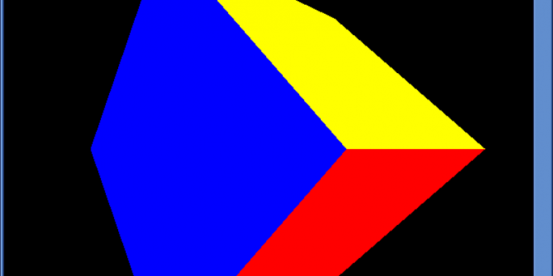
With all of this done, we finally get the cube rendered the way we want it:

Conclusion
Congratulations! You have just rendered your first 3D scene using Warp3D Nova. It was quite a bit of work to get here.
The 3D image still looks kind of flat. That's because there's no lighting. I'll introduce you to lighting models next time, and we'll render a more realistic looking cube.
Any questions or comments? Leave them below (or contact me privately).
Download the complete source code: W3DNovaTutorial5.lha


Post your comment